Ellis Circuit 7812 Circuit Diagram перевод

L7812ABD2TTR. 497-6037-2. 497-6037-1. L7812ABD2T-TR-ND. Standard Package. 1,000. Order today, ships today. L7812ABD2T-TR - Linear Voltage Regulator IC Positive Fixed 1 Output 1.5A D2PAK from STMicroelectronics. Pricing and Availability on millions of electronic components from Digi-Key Electronics.
Regulator Ic 7812 Diagram Circuit

Here, pin-2 is common for a negative terminal that is shown within the circuit diagram. For stable use of this voltage regulator IC, the input voltage should not go beyond 28v. We know that 7812 IC is a linear voltage regulator and they drop power & emit it in the heat form. If we provide input as 15v 0.5 A to 7812 IC then it has 12 v 0.5 A of.
7812 Circuit Diagram ,Find Out Here

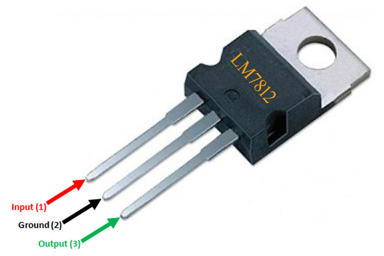
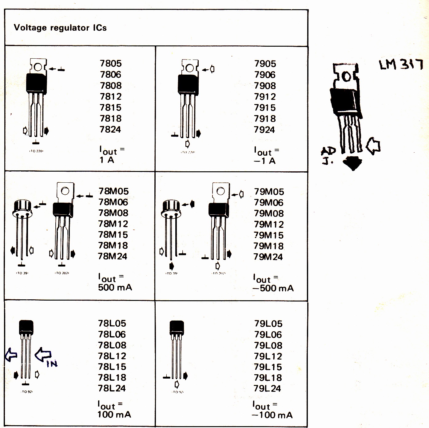
7812 circuit diagram. If you hold upside down (pins up) and the IC number is facing you then the left pin will be the voltage regulator output, the center pin will be ground and the right pin will be the voltage input pin. From my experience, the maximum safe current you can get from one 7812 IC is 1A. If you need more power then there are a.
LM7812 voltage regulator working and wave form animation,how to work voltage regulator YouTube
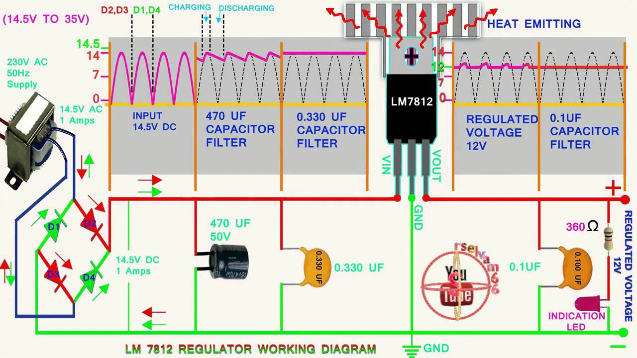
They can be a fixed regulated power supply source. They give output voltage: 5V, 6V, 9V, 10V, 12V, 15V, 18V, 24V at 1.5A max current. It is easy to use, cheap, popular for a long time. Parts used in this below circuits are easily available in most of the local markets. Many Fixed Regulator Circuits 5V,6V,9V,10V,12V 1A using IC-78xx series.
12 Volt Dc Voltage Regulator Circuit Diagram Pdf Wiring Diagram

LM7812 Description. LM7812 is a TO-220 packaged positive voltage regulator IC of LM78xx series that is manufactured by many different electronic components manufacturers. It has synchronous rectification features as well as a wide frequency response and it is ease-of-use and available in very low cost. The IC provides fixed 12V output voltage.
Ic 7812 Internal Circuit Diagram

The 7812 regulator is used to maintain output at 12 volts and three TIP 2599 transistors are used to boost current. This is a costly circuit because of the high power components used.. This is the most simple voltage regulator circuit diagram in our website! Just got an IC LM117 and 4 passive components. You can adjust the output voltage by.
7812 Pin and Circuit Diagram
Typical Application Circuit of a 78XX Voltage Regulator. The circuit shown below is a typical application circuit of the 7812 IC. The circuit includes a power source, two capacitors, and the voltage regulator IC.. As we can observe through the voltage probe, when an input voltage of ~25V is provided through the 7812 IC, the output voltage we obtain is 12V DC.
Max Circuit Linear Regulated Power Supply Circuit Diagram Examples

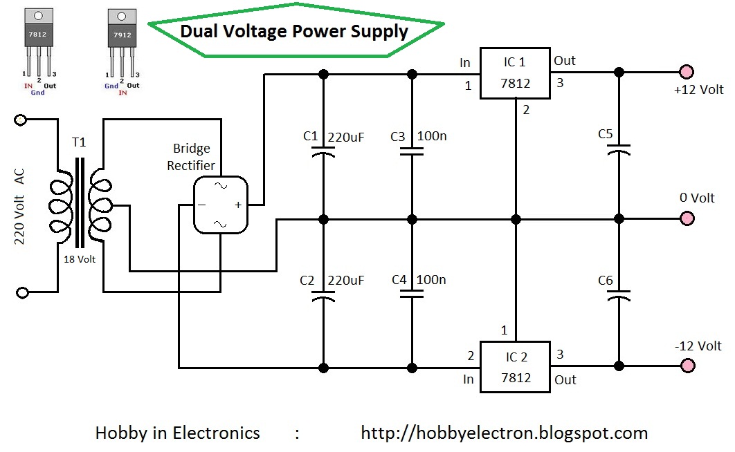
The above diagram showcases a +/-12 dual voltage or dual-powered circuit that uses a 7812 and 7912 pinout. Here the LM7812 IC regulator achieves +12V while the LM7912 regulator IC produces -12V. This Low current circuit can deliver no more than 1 Ampere, making it suitable to be used in a preamplifier tone manager that has an AMP-OP course.
Lm7812 Voltage Regulator Ic Pinout Datasheet Circuit And Specifications Vrogue
7812 Voltage regulator is a type of self-contained fixed linear voltage regulator integrated circuit. The IC belongs to ic 78xx voltage regulator family. The 7812 voltage regulator IC is ease-of-use and available in very low cost. The last two digits of 7812 indicates the output voltage that is 12 V. The ic 7812 is a positive voltage regulator.
Product Authenticity Guarantee Effortless Shopping L7812 CV Positive Voltage Regulator IC
LM7812 IC Features / Technical Specifications: TO-220 Package. The Output current is 1.5 Ampere. Immediate short circuit shutdown function. Immediate over heat shutdown function. Low price. Authentic to use in commercial devices. Accurate and fixed 12V output. Maximum input voltage is 35V DC.
7812 Voltage Regulator Circuit Diagram
Short circuit protection. Output transition SOA protection. 2 % output voltage tolerance . Guaranteed in the extended temperature range. CAD Model. Symbol . PCB Footprints. 3D Models. L7812CV Schematic Diagram. Below is the L7812CV Schematic diagram. L7812CV Pinout. Below is the L7812CV Pinout: It has 3 pins as follows: Pin 1 is the positive input.
Simple 5v Power Supply Circuit
Voltage regulator circuit with LM7812.. Input: 15-30V, Output 12V My Channel: https://www.youtube.com/user/Stefano91ste My WebSite: http://stefano91ste.alt.
Pin on Electronics

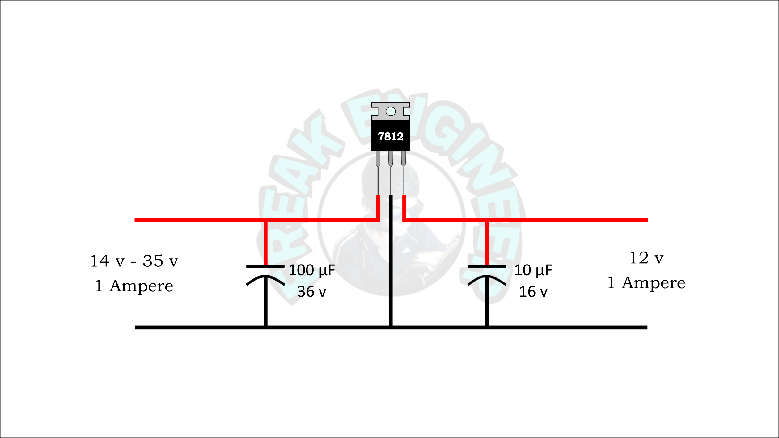
7812 IC voltage regulator circuit diagram. Components Needed. Power supply with an input range of 14 to 35V DC at 1A. Capacitors: 10uF/16V and 100uF/36V. 7812 IC. Soldering iron and connecting wires. Choice of breadboard or Veroboard. Circuit Explanation. Start by placing the 7812 IC onto the VEROboard or breadboard.
7812 Voltage Regulator Circuit Diagram Internal
7812 is a voltage regulator IC that provides 12 v output when an input voltage of 14 v - 35 v is provided. The DC input is applied to pin number 1 and 2 and the output DC voltage is obtained from pin 2 and 3. Where pin 2 is common for negative terminal as shown in circuit diagram. For constant use of the IC, input voltage should not exceed 28v.
[DIAGRAM] Circuit Diagram Of 7812 Voltage Regulator
2V DC power supply circuit using 7812 IC. LM7812 Internal Block Diagram. 7812 Applications. It used for dual power supplies; Mobile phone chargers; Children toys circuits; Used in distribution circuits; Current limiter circuits has this component; What is the purpose of LM7812? LM7812 is a linear voltage regulator that produces 12 volts.
LM7812 Voltage Regulator IC Pinout, Datasheet, Circuit, And, 40 OFF
National Semiconductor was an American semiconductor company that was founded in 1959. The company was known for its innovations in the field of analog and mixed-signal integrated circuits and was a leading supplier of power management and data conversion products. National Semiconductor's products were used in a variety of applications.