3 Phase Motor Control Circuit Diagram Rig Electrician Training YouTube

2 Answers Sorted by: 1 I would guess that wiring for high voltage the motor would use all the windings. Correct.. and when wiring for low voltage it would only utilize half the windings. Incorrect - although you could if you only wanted half power. The answer is to connect the half-windings in parallel.
3 Phase Motor Wiring Relationship Attachment Diagram Wiring23

Step 1 Turn off the power supplying the circuit to be wired to the motor. A three-phase motor must be wired to a three-phase supply. Video of the Day Step 2 Open the motor wiring box and identify the wires within. The nine wires should be labeled 1 through 9.
3 Phase Motor Circuit Diagram
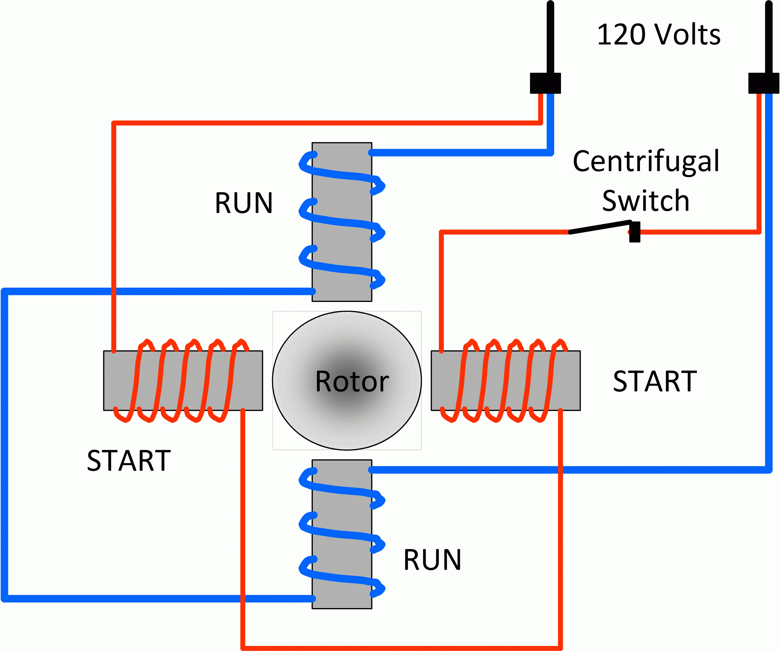
1 Check power source. Ensure that any electrical power fed into power cord, is shut off prior to working on motor. 2 Prepare power cord. Using a pair of diagonal cutters, cut and remove 3 in of rubber insulation around outside of power cord. Revealing four wires inside cord.
Three Phase Motor Power & Control Wiring Diagrams 3 Phase Motors
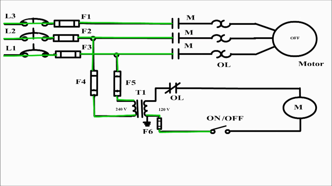
A 3 phase motor is a type of motor that operates with three separate phases of electrical power, and its wiring diagram depicts the connections between these phases and the motor itself. The 3 phase wiring diagram for motors typically includes information such as the voltage and current ratings, the type of motor (e.g., induction motor or.
3 phase motor wiring diagrams 230v
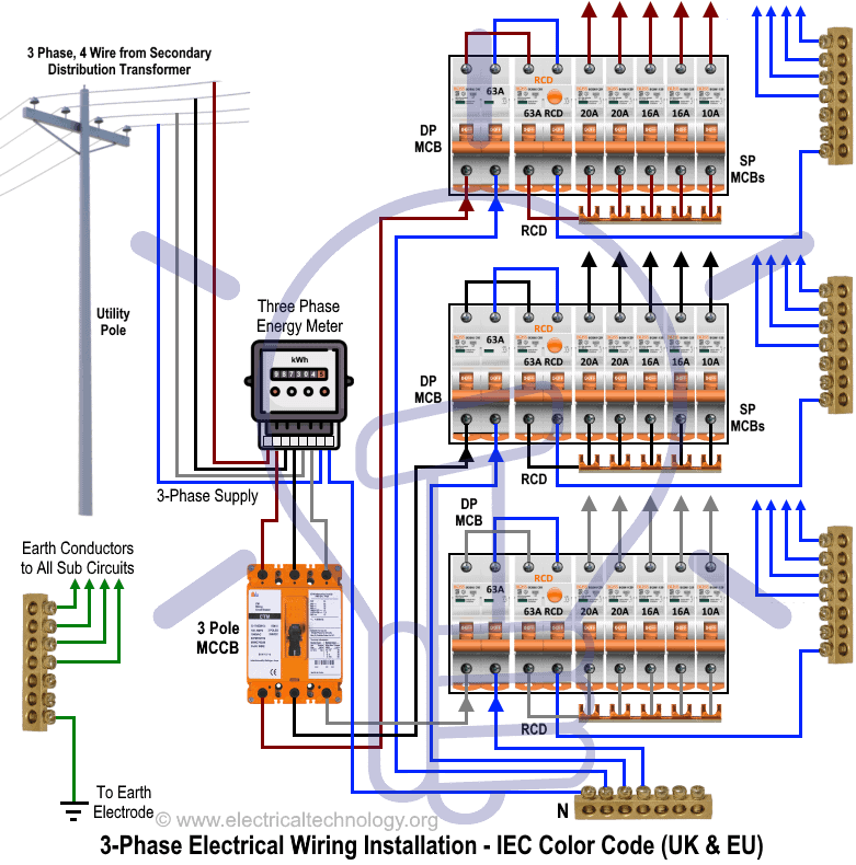
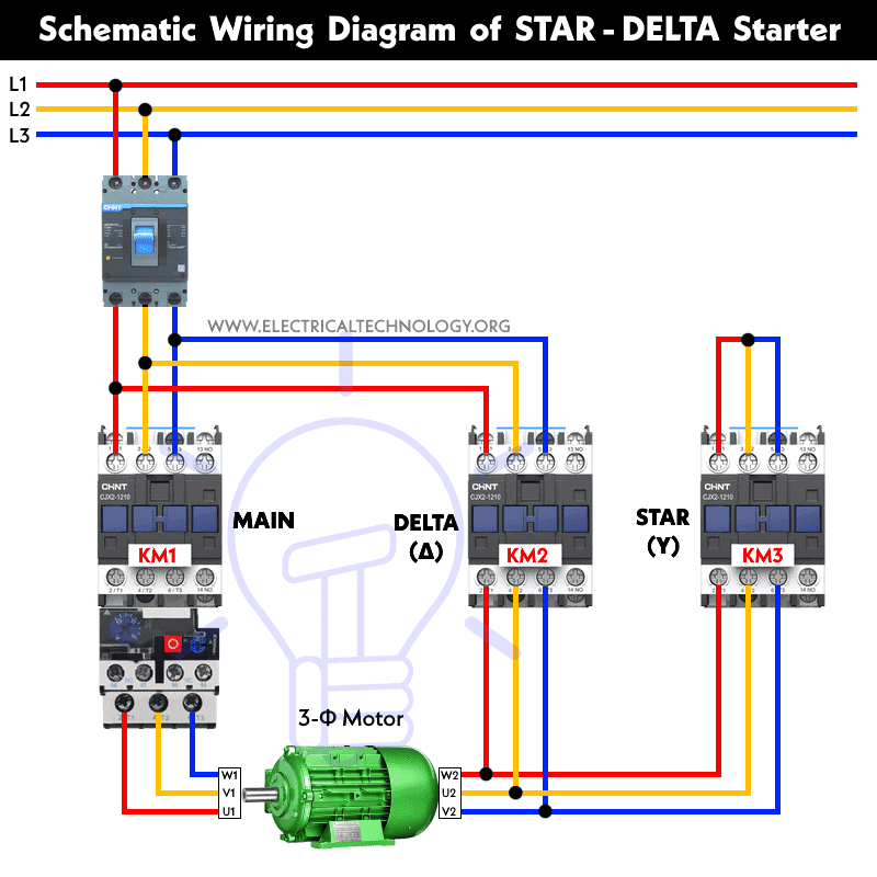
23 1 minute read Three Phase Motor Power & Control Wiring Diagrams Three Phase Motor Connection Schematic, Power and Control Wiring Installation Diagrams. Star-Delta (Y-Δ) 3-phase Motor Starting Method by Automatic star-delta starter with Timer. Three Phase Motor Connection STAR/DELTA Without Timer - Power & Control Diagrams
3 phase motor wiring Wire, Diagram, Motor

Step 1: Identify the Wires Identify and sort the 9 or 10 wires. 3 are power wires, and 6 or 7 come from the motor. The wires are color-coded, but some also have numbers written on them. Refer to the wiring diagram on the motor's label. Video | Wayne's Garage Step 2: Choose a Configuration Which configuration should you make?
Bestly 3 Phase Motor Control Panel Wiring Diagram

Section 2: Step-by-Step Wiring Process for a 9-Lead 3-Phase Motor. Wiring a 9-lead 3-phase motor requires a step-by-step process to ensure the correct connections are made. Below is a guide on how to wire a 9-lead 3-phase motor: Start by identifying the nine leads of the motor. These leads are labeled with numbers or letters, and each lead has.
Wiring Diagram 3 Phase Motor Switch Wiring Diagram
Wiring Diagrams ww introduction. (For 2 Phase, 3 Wire, L2 and T2 are common) Sgl. Phase Lines Sizes 0,l and 1P Single Phase. 2 Phase, 3 Wire (For separate winding motors only) WIRING DIAGRAMS w Bulletin 609U The Bulletins 609U and 609TU are the same as the standard Bulletin 609 Manual Starters except for the addition of Under-.
480v 3 Phase Motor Wiring Diagram Wiring Draw

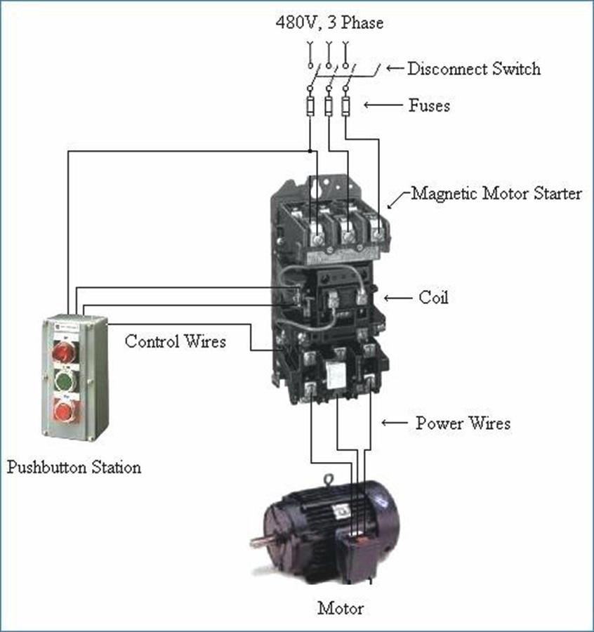
In a three-phase motor, the power supply is divided into three separate lines, each with its own phase. This type of motor is commonly used in industrial applications due to its efficiency and power output. Understanding the wiring diagram is essential when it comes to installing or troubleshooting a three-phase motor. The motor wiring diagram.
Wiring Diagram For Motor Starter 3 Phase Controller Failure Relay 3
Learn how to wire a three-phase motor properly for optimal performance and efficiency. Find step-by-step instructions and diagrams to help you understand the process and avoid common mistakes. Discover the benefits of using a three-phase motor and how to troubleshoot common wiring issues. Improve your electrical skills and ensure safe and reliable operation of your three-phase motor with our.
Wiring A 3 Phase Motor перевод Kira Wiring

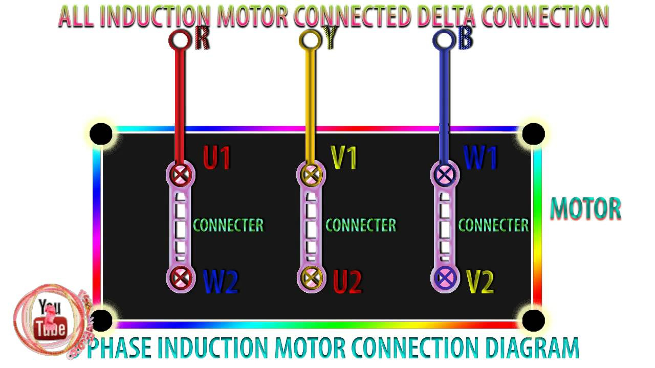
Three phase motor wiring diagrams are composed of three separate lines, each representing a power phase, and the lines typically form a closed loop. All three lines form a neutral wire, with each being either connected to the other two or completely independent.
230v 3 Phase Motor Wiring Diagram

Three-phase synchronous motors can be purchased with a variety of wiring styles. The most common is nine-wire, but there are also many examples of motors with three, six, or even twelve wires. Of all types, the twelve-wire motor provides the most options for connecting based on voltage and system configuration (wye or delta).
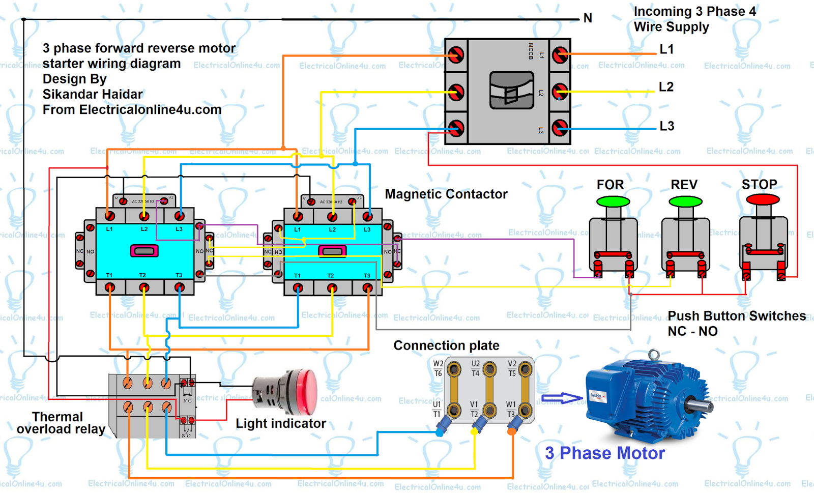
Forward Reverse Motor Control Diagram For 3 Phase Motor
The most common type of three-phase motor is that which has nine labeled (and often colored) wires coming out of the box on the side. There are many motors with more or fewer wires, but nine is the most common. These nine-wire motors may be internally connected with either a Wye (star) or a Delta configuration, established by the manufacturer.
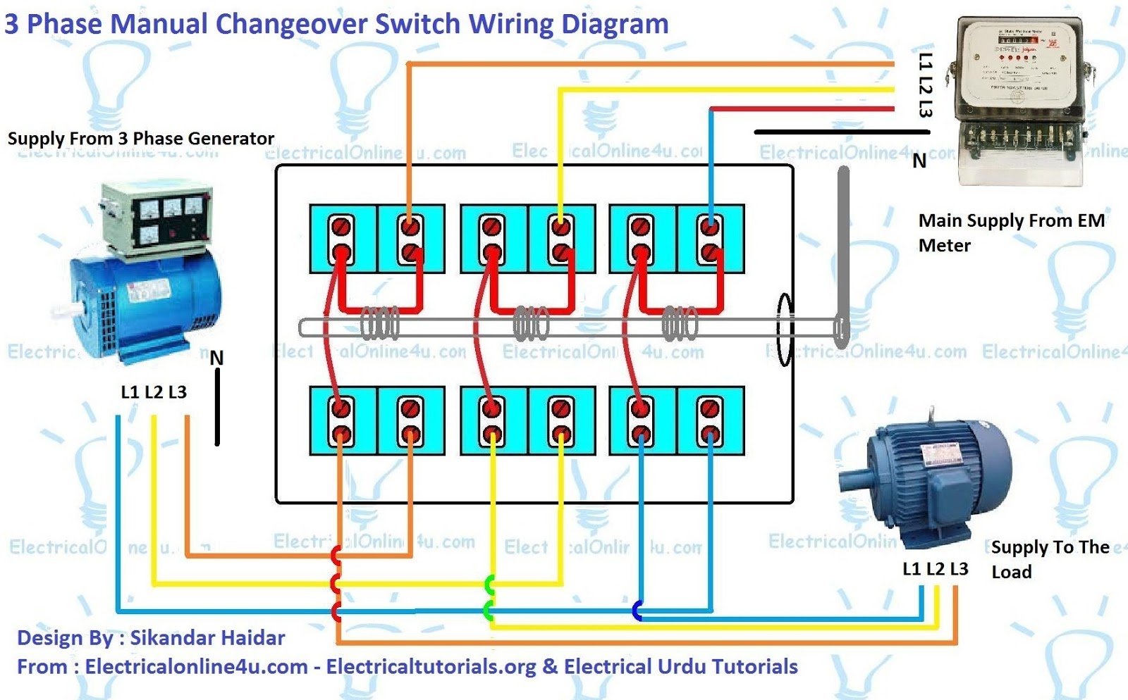
3 Phase Manual Changeover Switch Wiring Diagram For Generator
Three Phase - 3 Lead Motor. Find 3 Phase Electric Motor Wiring Diagrams for 12-Lead Motors, 9-Lead Motors, 6-Lead Motors, and 3-Lead Motors here.
Electric Motor Wiring Diagrams 3 Phase
The wiring diagram for a 3 phase motor is a visual representation of how the motor is connected to the power supply. It shows the connections between the power source, the motor windings, and the control circuitry. By understanding the wiring diagram, technicians and electricians can properly install and troubleshoot 3 phase motors.
3 Phase Motor Control Panel Wiring Diagram Home Wiring Diagram

There are two main wiring schemes in a typical 3-phase motor. Wye-Wound The technician can see both ends of 3 of the coils, and one end of the other 3. The remaining 3 ends are connected together inside the motor. In the diagrams below, the coils are represented with bold lines between terminal numbers on the far right side.